Have you ever wondered why most pressure vessel design firms are using finite element method for their design by analysis of pressure vessels?
I will demonstrate in this article that it is possible to get allowable pressure for design with several methods and which one is the most efficient to save material and money.
The three divisions of the ASME BPVC Section VIII standard introduce different ways to calculate the allowable pressure for design.
Division 1 was written long time ago when engineers didn’t even have computers. Until 1963, all pressure vessels were designed using this systematic “Design by Formula” approach, which was based on experience and simple mechanics. What were mostly concerned were how to keep hoop stress low with respect to yield, and how to use ductile material to accommodate local peak stresses.
In the DBF, the vessel geometry and major dimensions such as radius, length, etc. are specified, and then the required thickness is calculated for a given load using equations and graphical data. This approach gives a very high margin of safety, and leads to a conservative manufacturing process.
Division 2 was introduced later to allow better design which optimizes manufacturing process and decreases production costs. Based on firmer engineering theories, Division 2 introduced more complex and accurate formulas. With this new method, the design obtains higher allowable stresses and thus decreases the costs of materials.
This article is not a full comparison of Division 1 and 2. The purpose is to demonstrate that material can be saved even on a very simple example.
DBR (design by rule) and DBA (design by analysis) have both different approaches and formulas and I will use those formulas to compare the results.
Those calculations are quite simple, but they are also very useful to understand why there is a huge potential to save money by changing to a different design method.
The example I will talk in this post is a simple cylindrical shell that will be subjected to an internal pressure. The material used is carbon steel, ASME material specification SA-516-70, as this is one of the most commonly used materials in the fabrication of pressure vessels.

The values of allowable stresses are mentioned in the Section II Part D Tables 5A and 5B. These allowable stress values are calculated by applying a safety factors to both the minimum tensile strength and the minimum yield strength and then setting the lower of these two values as the maximum allowable stress at each temperature.
For Division 2 stress safety factor are defined as 2.4 for the minimum tensile strength and 1.5 for the minimum yield strength
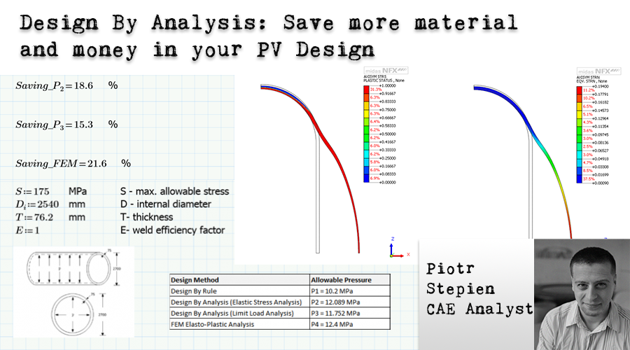
1.Design pressure according to Design By Rule. ASME BPVC Section VII Div.2 Part 4.3.3.1

2.Design pressure according to Design By Analysis using the Elastic stress analysis method. ASME BPVC Section VII Div.2 Part 5.2.2.1

3. Design pressure according to Design By Analysis using the Limit-Load analysis method. ASME BPVC Section VII Div.2 Part 5.2.2.3

4. Elasto Plastic FEM Analysis
FEM Elasto-plastic Analysis have been performed using the software midas NFX.

The study has been performed on a 2D Axisymmetric model which represents a section of the pressure vessel. Material model used is Elasto-Plastic model and hardening was defined through the true-stress-strain function.


Model has been meshed with elements of size 25 mm to ensure to have at least 3 elements in the thickness of the section.

After application of the boundary conditions and the pressure load on the internal face of the pressure vessel, a nonlinear static analysis case has been created and analysis has been performed.
The results tell us that the plastic load has been reached for a pressure of 29.76 MPa and finally it gives a design pressure of 12.4 MPa.


Here is the Full Step-by-Step Analysis Video:
5.Comparison of the results obtained with the four different methods.

If we compare those results, it is obvious that the Design By Rule is the most Conservative Method which leads to a lower allowable pressure and thus more expensive pressure vessel design. Both Design by Analysis Methods (Elastic Stress Analysis and Limit Load Analysis) give a higher allowable pressure, which leads to further savings.
FEA Elasto-plastic Analysis is actually the most accurate method because it takes in account the plastic hardening behavior to calculate the allowable pressure. FEA Results provide also the highest allowable pressure and lead to more savings of material.
This simple calculation of the savings gives you a small idea of the cost reduction of your pressure vessel design in function of the method used.

And You, what is the best saving you did using Finite Element Analysis?
Share your experience in the comments!
GET THE FREE GUIDE
24 Links and Articles to know about Pressure Vessel Design and Simulation
This is quite the complicated article! I was not expecting to see so many calculations and explanations to go along with this type of thing, but then again, it is fabrication so it makes sense. Comparing the results, like you suggest, is a great tip.
I like the comparison your providing but it looks like a few corrections are needed. In Case 3 you state you using the Limit-Load analysis method per Part 5.2.2.3. This part of the code is associated with Elastic Stress analysis not Limit-Load analysis. Where did this equation come from? Also, you’re referring to Section VII not Section VIII within most of your references. Within Case 2 shouldn’t the cylinder hoop stress calculate to be 515 MPa not 516.355 MPa?
Simplified engineering methods (such as in the Rules or some Codes) created on the basis of experiments, and some “safety factors”-coefficients (which based on statistical methods) are laid into them. So there is the difference. In some countries all the structures are divided by “categories of responsibility” depending on the use of structures (for example, the number of people near him in exploitation period: more people – more reserve for strength of materials)
I have not read the original ASME and just ran my eyes over the article, so that I could write a little off topic. In that case sorry 🙂
This was a good article that I was looking for since the introduction of DBA approach in lieu of DBR approach in ASME Sec VIII Div 2. Thanks for taking up this topic.
However I did not understand the formula you applied to find the MAWP P2 in case of elastic analysis. What is the allowable limit for Von-Mises equivalent stress as per ASME Sec VIII Div 2 code ?. As per my knowledge, code specified allowable limits for Primary, Secondary stresses independently and with different combinations.
Also could you provide the reference for formula you have used in slide for limit load analysis.
Thanks Parikshit, I am glad that you like it!
Where can i find stress-plastic strain data ?