Today’s article has been generously written by Etienne Thepenier, who wanted to share his experience on cold forged fastener simulation using FEA.
Here is Etienne’s Linkedin if you wish to contact him.
By the way, Etienne is French (like me) which means we have great participation from French engineers in this blog… Even if we are not basically English speakers… 🙂
OK, let’s talk about Forging simulation now:
Forging is a manufacturing process, which shapes work pieces by applying compressive forces onto them, using hammers or presses. The processes are generally classified into two main families according to materials forged and the forging temperature.
– “Cold” forging deforms metal while it is below its re-crystallization point.
– Over this point, the process is named “hot” forging.
Finite Element Method (FEM) is used to model products in virtual environments. In the forging industry, this method is used to solve various kinds of studies, for example; new product validation, forging cycles design, presses tooling design and optimization, parts quality improvements, R&D, etc.
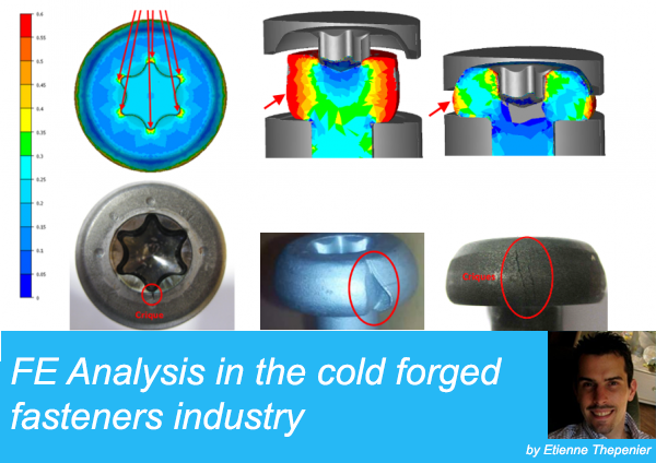
In the following, I will present to you the reliability of this tool with some examples of the activities I perform as an R&D engineer in a cold forging company which manufactures fasteners for the automotive industry.

1 – FEM in the forging industry
The Finite Element Method is an approximate numerical calculation method that solves partial differential equations of models divided into mesh elements and nodes.
Parts to be analyzed are divided into several elements, connected by nodes; this is the meshing operation.
These nodes are like a glue that combine all of the elements into one assembly.
The physical behaviour of each element is defined by algebraic equations.
The number of these equations is very large (thousands, millions).
The use of a computer is essential.

In the forging industry, the FEM are mainly used to:
– Design forging cycles & tools
– Optimize the problematic tools
– Optimize the problematic forging cycles (parts quality)
– Produce feasibility and R&D studies
FEM Outputs (not exhaustive):
| Parts: | Tools: | Presses: |
| – Shape filling
– Velocity- Folds occurs – Internal stress – Damage criteria’s – Hardness (HV) – Temperature |
– Die abrasion wear
– Contact time – Internal stress – Damage criteria’s – Hardness – Fatigue |
– Press rating per station
– Cumulated press rating – Apron torque evolution |


 |
 |
2 – Finite Element Method reliability
The quality of the results (outputs) depend directly on the input quality. It has to be increased by constant team work which requires permanent feedback from the manufacturing services (including forged parts measurements), and an optimization of the numerical models parameters (friction coefficient, etc). For example, when I have to suppress a defect on a part, my first goal is to model the current forging cycle to obtain the “same” defect from FEM. Only after this, I can work on various proposals to remove it.
 |
 |
See below, some examples of chaotic results obtained by FEM in order to validate the numerical models. 
3 – Feasibility studies
– Validate product feasibility.
– Define preliminary forging cycles, kinds of tooling and machines to be used.

4- Forging Cycle Design
Goals:
– Define the optimal cold forging cycle and the press to be used.
– Define materials to be used (on parts and tooling).
– Design the tooling.
After having obtained a customer order for a complex part, FEM is then used to design the optimal forging cycle and tooling presses.
During this step, each part and press tooling parameter is checked to prevent parts defects and tooling damage.
Using FEM on this step improves our risk management and productivity by reducing lead-times and tooling costs.


Outputs checked:
– Parts defects: cracks, folds, etc.
– Presses tonnage
– Tooling stresses
– Shapes validation
– Dimensional tolerances
– etc.

5- Tooling Lifetime Optimization
Goal:
– Modify tooling design to increase lifetime
When mass production of parts starts, tooling lifetime can be under the “average.” FEM can be used to understand phenomena which reduces the lifetime of the tool, so as to improve the tool and thus increase the lifetime. For this kind of studies, tooling has generally to be modelized as elasto-plastic material. After the analysis, tooling lifetime can be improved and validated by FEM by changing many parameters such as tooling materials, forging cycles, tooling design, etc


6- Suppression of parts defects
Goal: – Define materials / cold forging ranges to defects (cracks, bending, lacks, etc.) For various reasons, some defects can appear randomly on forged parts. In this case, FEM is use to understand the phenomena and remove defects such as cracks, rafters, folds, lacks of material, non-conforming shapes, etc. This type of study increases the productivity and reduces scrap and sorting costs. and sorting costs.


7- Product Analysis
Goals:
– Design parts to fit functional requirements.
– Understand part breaks/defects and propose new designs to fit functional requirements.
FEM can also be used to design screws in order to pre-validate these in work conditions and/or to estimate their limits.
On the example below, the C1 dimension was originally too thin, so the washer and the screw flange were permanently deformed before the shank break, which is not allowed. FEM was used to define and validate a new C1 dimension.

Manufactured test model until break
New screw design until break
8- Conclusion
As presented above, FEM in cold forging can be used for many kinds of studies.
Its benefits are the following:
It reduces:
Prototyping costs:
– It allows testing and optimizing various technical solutions.
– It reduces test tooling manufacturing costs.
– It reduces the lead-time.
Non-conformity costs:
– It is used to suppress part defects: cracks, folds, material lacks, etc.
– It is used as a continuous improvement tool to optimize the manufacturing process.
It increases:
Complex parts development knowledge:
– It increases our customer confidence.
– It allows us to penetrate new markets.
– It optimizes product quality to meet customer requirements.
Tools and presses lifetime:
– It performs the stress localizations.
– It improves the presses equilibrium.
– It designs the pre-loaded tools.
Thank you for reading this study about FEM usage in the cold forging industry, I hope it was beneficial to you!
If you have experience in this area, please leave some comments below
GET THE FREE GUIDE
24 Links and Articles to know about Pressure Vessel Design and Simulation
Hi
Your “FE analysis in the cold forged fasteners industry”
mostly acts like a picture. Videos and opening parts like e.g
“choose the Right FEA software” are not working.
Gives “ internet explorer has stopped working “ error.
I used too much time for correct it. No result.
for sure it is not my computer problem.
It is so good article. Please fix demonstration error.
thanks for sending such good article.
mohammad
Hi Mohammad,
I corrected the first video, let me know if it works now.
Thanks for noticing!
Can you let me know by email other things that are not working?
Cyprien