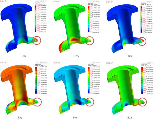
In the finite element method, when structural elements are used in an analysis, the total stress distribution is
obtained. Therefore, to produce membrane and bending stresses, the total stress distribution shall be linearized on a stress component basis and used to calculate the equivalent stresses.
If shell elements (shell theory) are used, then the membrane and bending stresses shall be obtained directly from shell stress resultants.
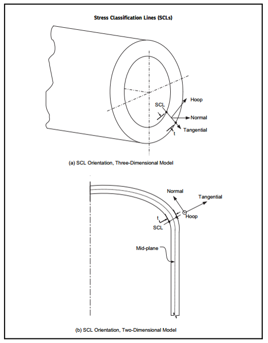
Membrane and bending stresses are developed on cross sections through the thickness of a component. These sections are called stress classification planes (SCPs). In a planar geometry, a Stress Classification Line (SCL) is obtained by reducing two opposite sides of a SCP to an infinitesimal length.
SCPs are flat planes that cut through a section of a component and SCLs are straight lines that cut through a section of a component. SCLs are surfaces when viewed in an axisymmetric or planar geometry.
Understanding stress linearization
Stress linearization is the separation of stresses through a section into constant membrane and linear bending stresses. To linearize stresses, the following procedure is used:
- You define a section through your model. You specify the endpoints of the section by selecting nodes in the model, coordinates in space, or a saved path.
- Your EA software defines the stress line by interpolating between the two endpoints to obtain a user-specified number of equal intervals along a straight line.
- You can save the stress line as a path; the saved path includes the endpoints and each interval point along the stress line.
- The specified stress results are obtained at equally spaced intervals along the line in a local coordinate system defined by the line.
- Your FEA Software performs stress linearization calculations and displays the results in the form of an X–Y plot. You can choose to save the data and/or to write it to a file.
If you linearize stresses across multiple part instances, the results will be averaged for any points that exist in more than one part instance.
Stress Integration Methods
The following three approaches are provided for linearization of finite element results.
(1) Stress Integration Method–This method can be used to linearize stress results from continuum finite element models [Ref. WRC-429].
(2) Structural Stress Method Based on Nodal Forces–This method is based on processing of nodal forces, and has been shown to be mesh insensitive and correlate well with welded fatigue data [Ref. WRC-474].
(3)Structural Stress Method Based on Stress Integration–This method utilizes the Stress Integration Method, but restricts the set of elements that contribute to the line of nodes being processed.
*The Structural Stress Method based on Stress Integration is recommended unless another method can be shown to produce a more accurate assessment for the given component and loading condition. This method matches the Structural Stress Method Based on Nodal Forces, which is insensitive to mesh refinement. In addition, this method can be performed with post-processing tools typically provided by commercial finite element analysis software.
SELECTION OF STRESS CLASSIFICATION LINES
Pressure vessels usually contain structural discontinuity regions where abrupt changes in geometry, material or
loading occur. These regions are typically the locations of highest stress in a component. For the evaluation of failure modes of plastic collapse and ratcheting, Stress Classification Lines (SCLs) are typically located at gross structural discontinuities. For the evaluation of local failure and fatigue, SCLs are typically located at local structural discontinuities.
For SCLs that span a material discontinuity (e.g. base metal with cladding), the SCL should include all materials and associated loadings. If one of the materials, such as cladding, is neglected for strength calculations, then only the base metal thickness should be used to calculate the membrane and bending stresses from the linearized forces and moments across the full section for the evaluation of plastic collapse.
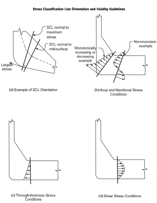
To most accurately determine the linearized membrane and bending stresses for comparison to elastic stress limits, the following guidelines should be followed. These guidelines can be used as a qualitative means to evaluate the applicability of different SCLs. Failure to comply with any of these criteria may not produce valid membrane and/or bending stresses. Application of the limit load or elastic-plastic analysis methods in Part 5 is recommended for cases where elastic stress analysis and stress linearization may produce ambiguous results.
*SCLs should be oriented normal to contour lines of the stress component of highest magnitude. However, as this may be difficult to implement, similar accuracy can be obtained by orienting the SCL normal to the mid-surface of the cross section. SCL orientation guidelines are shown in Figure 5-A.3.
Here is a video tutorial about stress linearization:
Hope this is useful !
Let me know if you see something to correct in this article
GET THE FREE GUIDE
24 Links and Articles to know about Pressure Vessel Design and Simulation
Nice article; it gives a lot of information in a short space; I used to do a lot of stress linearization when analyzing stress for pressure regulators with ANSYS.
One issue I remember I had was that it was not possible to use linearization in the same time with symmetry; and I had to analyze the whole model.
From what I see, NFX doesn’t have that problem.
Thanks for the article.